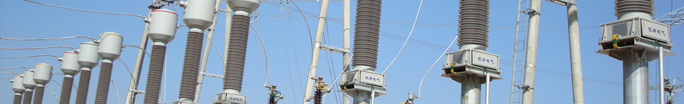
Product use:RIP condenser transformer/reactor bushings are mainly used in power transformers/reactors, working as the current carrying conductors for pulling in or drawing high, medium and low voltage side current of transformers/reactors, and playing a role of insulation for oil tank shell of transformers/reactors.
Service conditions:
· Altitude: 1000m (products can be designed according to altitude correction coefficient if altitude is higher than 1000m)
· Ambient air temperature: -45℃- +60℃
· Installation angle: arbitrarily
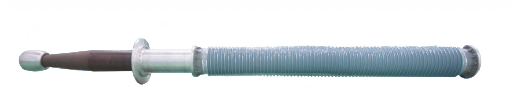
Product structure: it is mainly composed of conducting pole, RIP capacitor core, high temperature liquid silicone rubber composite external insulation, equalizing ball, test tap, fittings, etc.
Advantages of bushings:
Ø Unique resin system and special buffer strips
Ø The most advanced production equipment of the world guarantee the better electrical properties, heat-resistance and mechanical properties of RIP bushings series.
Ø The lower weight and smaller volume make it easy for transportation, erection and maintenance.
Ø Oil-free and gas-free design is more environmentally friendly, no risk of explosion;
Ø Excellent performance ensures long-term stable online operation.
Description of product type
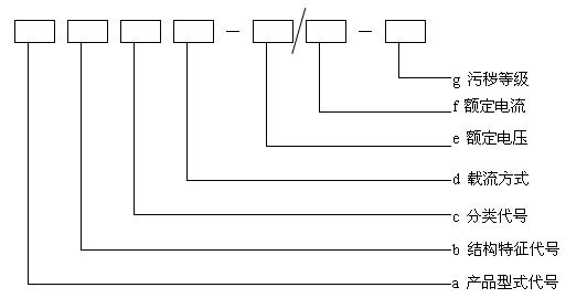
a Product type code
· BRFG Composite insulated RIP condenser transformer bushing
·BRCG Porcelain insulated RIP condenser transformer bushing
·BRQG Oil- SF6 RIP condenser transformer bushing
·BROG Oil- oil RIP condenser transformer bushing
· CRFG Composite insulated RIP condenser wall bushing
·CRCG Porcelain insulated RIP condenser wall bushing
· DRFG Composite insulated RIP condenser generator bushing
·GRFG Composite insulated RIP condenser GIS outlet line bushing
b Structural features code
L means it can be equipped with current transformers; no L means it can not be equipped with current transformers.
c Classification code
DC bushings are indicated with the letter Z; AC bushings are not expressed.
d Way of current carrying
1-Direct type;2-Cable through type
TableⅠ Electrical performance table of oil - air dry-type condenser transformer/reactor bushings
|
Systemic nominal voltage Un kV
|
35
|
66
|
110
|
132
|
150
|
220
|
330
|
420
|
500
|
|
Rated voltage Ur kV
|
40.5
|
72.5
|
126
|
145
|
170
|
252
|
363
|
420
|
550
|
|
Maximum working phase voltage for equipment Ur/ kV kV
|
23.5
|
42
|
73
|
84
|
98.5
|
146
|
210
|
242
|
317
|
|
60s Power frequency withstand voltage
|
Dry kV (r.m.s)
|
95
|
155
|
255
|
305
|
355
|
505
|
625
|
695
|
870
|
|
Wet kV(r.m.s)
|
80
|
140
|
230
|
275
|
325
|
460
|
535
|
680
|
790
|
|
Lightning impulse withstand voltage
|
Full wave kV (peak)
|
200
|
325
|
550
|
650
|
750
|
1050
|
1175
|
1425
|
1800
|
|
Chopped wave kV (peak)
|
-
|
-
|
635
|
750
|
865
|
1210
|
1495
|
1639
|
2070
|
|
Switching impulse withstand voltage (dry or wet) kV (peak)
|
-
|
-
|
-
|
-
|
-
|
850
|
950
|
1050
|
1300
|
|
Dielectric loss %
|
Added value (not more than)
|
1.05Ur/ - Ur: 0.1
|
|
Maximum value
|
40.5kV - 363kV
|
0.6, measured at the voltage of 1.05Ur/
|
|
420kV - 550kV
|
0.5, measured at the voltage of 1.05Ur/
|
|
Partial discharge at the voltage of Ur (not more than) pC
|
10
|
Schematic diagram of 72.5kV and 126kV dry-type condenser transformer bushing
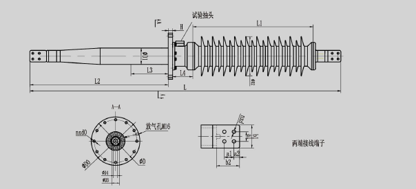
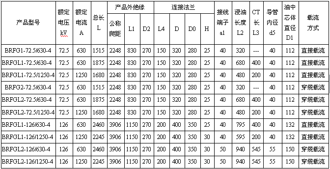
Main dimensions of 72.5kV and 126kV dry-type condenser transformer bushings
Unit:mm
Schematic diagram of 145kV and 170kV dry-type condenser transformer bushing
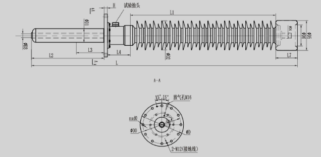
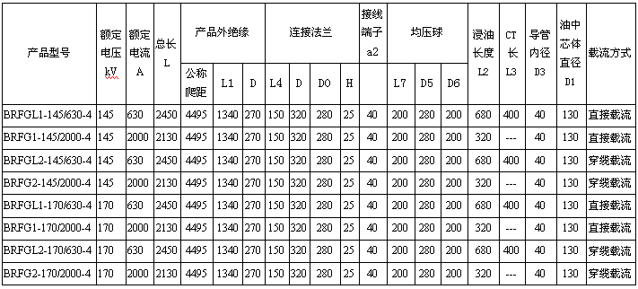
Main dimensions of 145kV and 170kV dry-type condenser transformer bushings
Unit:mm
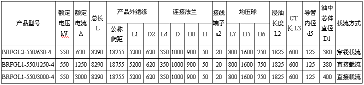
Schematic diagram of 252kV and 550kV dry-type condenser transformer bushing

Main dimensions of 252kV dry-type condenser transformer bushings
Unit:mm
Main dimensions of 550kV dry-type condenser transformer bushings
Unit:mm